


UV-C Technology in HVAC Systems
Biofilm that builds up on the cooling coils of air handling units (AHUs) cuts heat transfer, makes chillers, pumps and fans work harder, and degrades indoor air quality. This article summarizes the scientific evidence on germicidal UV-C technology for coils, the relevant ASHRAE references, how it connects to WELL and LEED, and the Light Progress solutions. It is written for HVAC engineers, energy managers, facility managers, and those responsible for healthcare and certified buildings.
A Problem You Can’t See but Still Pay For
Cooling coil surfaces bring together everything microbes need to thrive: constant moisture, darkness, condensate, and temperature swings. Biofilm forms on them — a matrix of bacteria, mold, and spores that clings to the fins and steadily erodes system performance.
Biofilm acts as a thermal insulator and narrows the free area available to the airflow. The chiller has to work harder, pumps run against higher resistance, and fans make up for a growing pressure drop. At the same time, a fouled coil can release biological particles into the supply air. Independent scientific literature, listed in the sources at the end of this article, has documented and quantified these effects.
Biofilm is not just settled dirt: it is a living microbial matrix that starts to re-form right after mechanical or chemical cleaning. Finned coil surfaces, condensate drain pans, and internal joints create sheltered microenvironments where bacteria, mold, and yeast multiply between one maintenance cycle and the next.
What Is Biofilm?
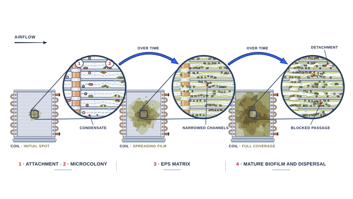
Biofilm is a community of microorganisms (bacteria, mold, and yeast) that attaches to a surface and encases itself in a matrix of extracellular polymeric substances (EPS) produced by the microorganisms themselves. The matrix holds water, nutrients, and particulate matter, and shields the cells from their surroundings — including cleaning treatments.
A cooling coil provides ideal conditions: fins wetted by condensate, dust and organic matter carried in by the airflow, and a steady supply of microorganisms. The resulting layer is slimy, tenacious, and grows thicker over time, cutting heat transfer and narrowing the air passages between the fins.
How it forms
|
1 — Initial attachment Airborne cells settle on the wet fins; the bond is still weak and reversible. |
2 — Irreversible attachment Microorganisms anchor to the surface and begin producing the EPS matrix. |
3 — Maturation Microcolonies grow into a layered structure that traps water, dust, and nutrients. |
4 — Dispersal Fragments and cells break away, are carried off by the airflow, and colonize new surfaces. |
Source: Donlan R.M., Costerton J.W., “Biofilms: Survival Mechanisms of Clinically Relevant Microorganisms,” Clinical Microbiology Reviews, 2002.
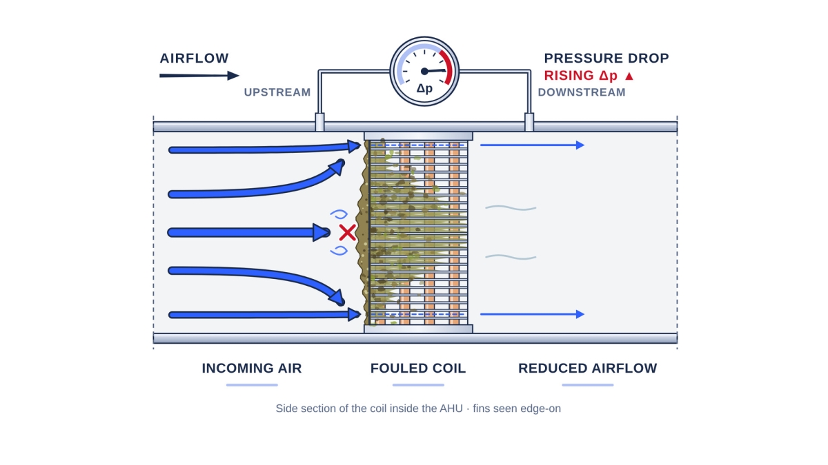
Coil cross-section: biofilm clogs the fins, raises the pressure drop (Δp), and restricts airflow.
The Limits of Conventional Cleaning
Chemical and mechanical coil cleaning remains essential, but it is intermittent by nature. Cleaning cycles happen at set intervals and leave windows in which biofilm grows back unchecked. For systems with steady thermal loads, the result is a recurring cycle of performance loss: chillers, pumps, and fans work harder just to reach setpoints that a clean coil would deliver.
To close that gap, facility operators are increasingly adding disinfection technologies that run continuously, 24/7, without interrupting operation — a shift from a reactive approach to preventive, ongoing control.
Mechanism: Why UV-C Works on Coils
Germicidal UV-C technology (germicidal wavelength of 254 nm) acts on the genetic material of microorganisms, preventing them from replicating. It leaves no chemical residue and does not build microbial resistance. Applied continuously to the coil and the condensate drain pan, it keeps surfaces biologically clean with no system shutdowns for cleaning, and over time helps restore design heat transfer conditions.
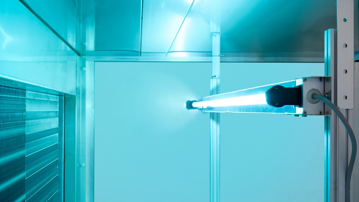
Light Progress UV-C lamp installed inside an AHU, in front of the finned coil.
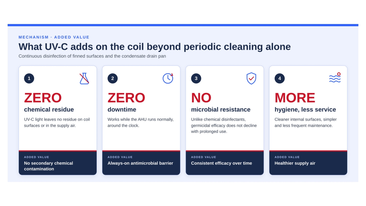
The added value of continuous UV-C disinfection on the coil compared with periodic cleaning alone.
One point comes through clearly in the scientific literature: the benefit is greatest when treatment starts on a new or clean coil. UV-C is a continuous preventive measure that complements maintenance — not a substitute for an initial cleaning.
The Benefits of Installation
|
Lower energy use A biologically clean coil restores heat transfer: the chiller works less, pumps face less resistance, and fans run against a lower pressure drop. In the Michigan study, chiller energy use dropped by as much as 28.2%. |
Indoor air quality Continuous coil disinfection targets one of the main sources of microbial contamination in conditioned air: bacteria, mold, and spores do not accumulate on the finned surfaces. |
Lower maintenance costs Continuous biofilm prevention reduces how often chemical and mechanical cleaning is needed, saving on labor, chemicals, and scheduled downtime. |
Closer to design conditions With clean coils, chillers, pumps, and fans run closer to their design conditions, with less stress on components. |
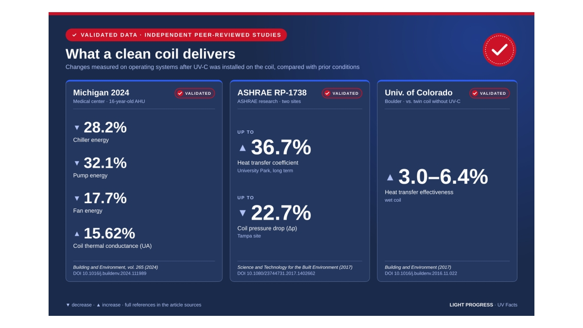
Validated data: values measured on operating systems and published in independent peer-reviewed studies (Building and Environment; Science and Technology for the Built Environment). Full references and DOIs are listed in the sources at the end of this article.
ASHRAE, WELL, and LEED: How UV-C on Coils Is Recognized
| Standard / Guideline | Relevance to UV-C on coils |
|---|---|
| ASHRAE Handbook — HVAC Applications | The chapter Ultraviolet Air and Surface Treatment (Chapter 62 in the 2023 edition, developed by Technical Committee 2.9) is the design reference for UV-C systems on coils, drain pans, and air. For cooling coils, the technical literature citing the Handbook indicates a minimum UV-C irradiance of 50–100 µW/cm² across the entire coil face, including the edges and corners of the plenum. |
| ASHRAE Standard 241 — Control of Infectious Aerosols | UV-C disinfection is recognized among the technologies for controlling infectious aerosols in buildings. |
| WELL Building Standard v2 — Feature A14 “Microbe and Mold Control” | Installing UV-C lamps on coils and condensate drain pans is one of the accepted solutions for mold and bacteria control, with a design based on modeled irradiance across coils, drain pans, and plenum corners. |
| LEED v4.1 | Controlling microbial contamination in AHUs can support the indoor air quality strategy under the EQ credit Enhanced Indoor Air Quality Strategies and, for projects with documented benefits, the Innovation credit. |
Where It Applies in the AHU
|
Heat exchange coils The primary application: lamps placed upstream or downstream of the coil keep the finned surfaces biologically clean around the clock, preventing biofilm and the loss of heat transfer and rise in pressure drop that come with it. |
Condensate drain pans Permanently wet environments that are critical for bacterial growth, including Legionella. UV-C treatment reduces the microbial load at the source, before microorganisms reach the conditioned air. |
High-humidity sections In sections with heavy condensation, typically cooling and dehumidification, UV-C provides a level of continuous control that complements thermal management and periodic cleaning cycles. |
Support between cleaning cycles Built into existing maintenance programs, UV-C technology slows biofilm regrowth between service visits and helps keep long-term operating costs in check. |
Light Progress Solutions for Coils
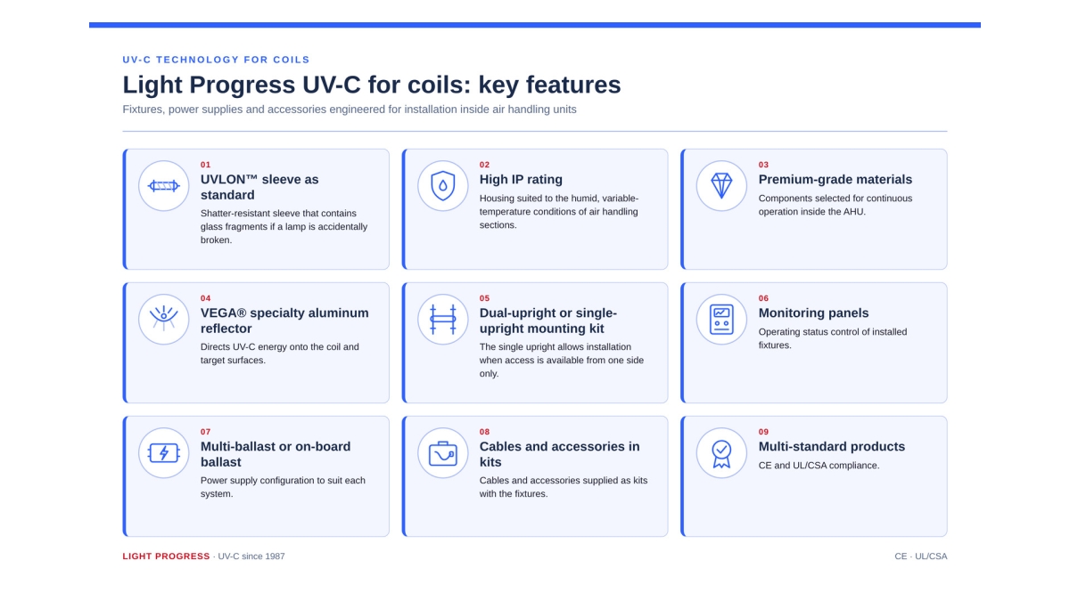
Key features of Light Progress UV-C solutions for AHU coil installations.
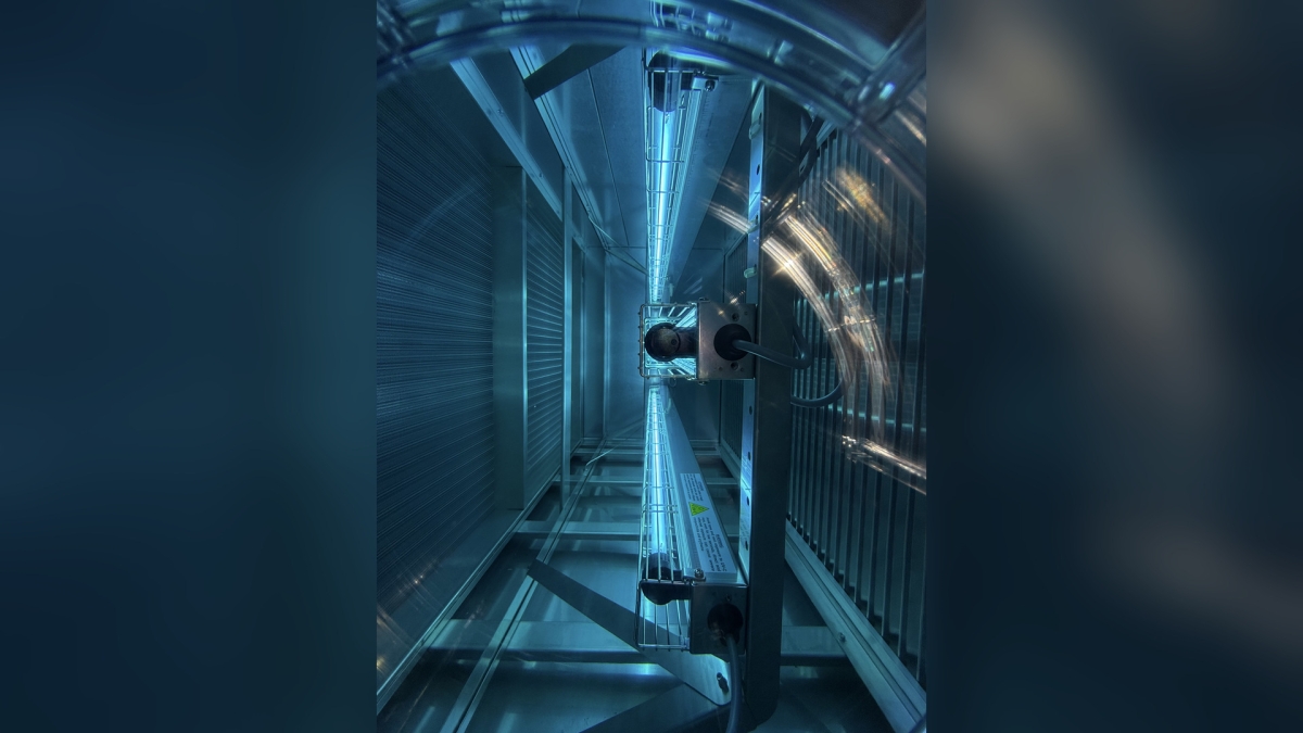
Light Progress UV-C lamps operating inside an AHU, mounted on an upright in front of the finned coil.
Sizing: The Online UV-C Configurator
|
Distance from the source UV-C intensity falls off quickly with distance from the lamp. Positioning relative to the coil determines whether the dose is adequate across the entire surface, including edges and corners. |
Air velocity and temperature On the coil, exposure is continuous and the dose builds up over time; however, airflow and air temperature affect lamp output, which must be corrected at the design stage. |
Coil geometry and shadow zones Fin depth, spacing, and angle create areas that light does not reach directly. The design identifies them and addresses them through fixture placement and, where needed, additional units. |
Moisture and organic matter Heavy deposits and organic matter shield surfaces and reduce the effective dose. A preliminary cleaning remains a prerequisite for full treatment effectiveness. |
The Light Progress UV-C Configurator
For UV-C coil sizing, Light Progress provides an online configurator, the dedicated tool for calculating the right solution for the AHU coil.
The configurator is also available as a DLL library for integration into AHU selection software such as AirCalc and CTA Pro, or into proprietary HVAC configurators.

Light Progress UVCALC-HVAC UV-C calculation software, developed in collaboration with the Thermodynamics and Heat Transfer research group at the University of Florence.
UV-CALC HVAC: Inputs, Results, and Configuration
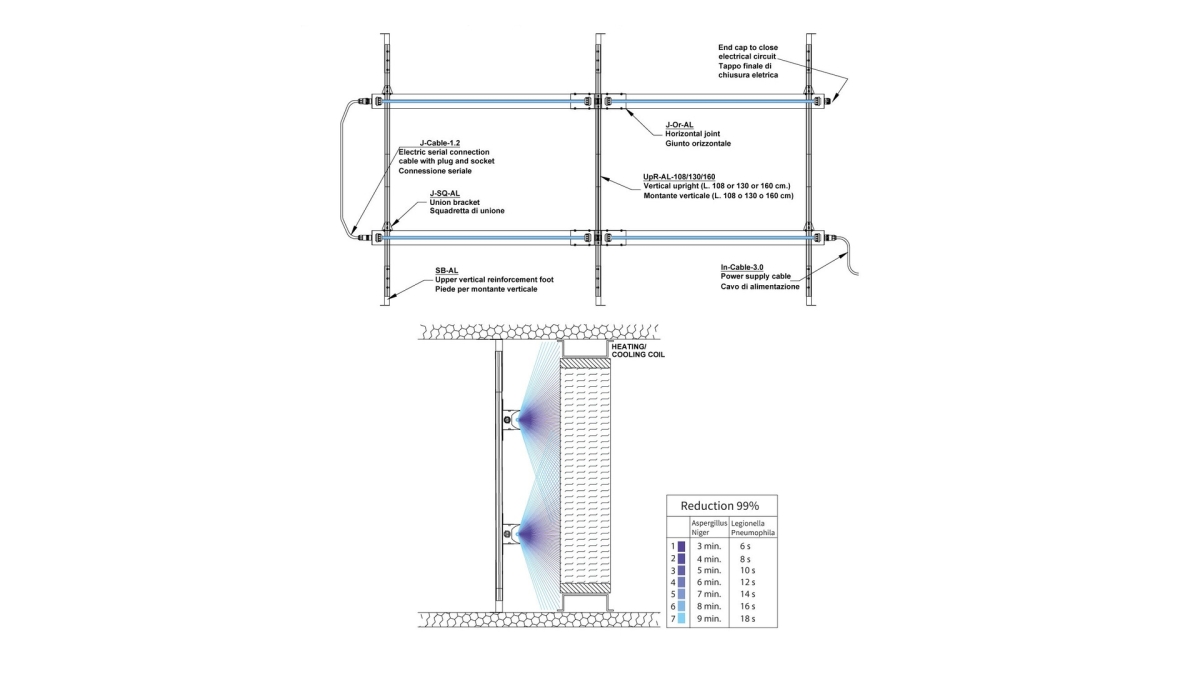
Example of configuration B2: indicative layout of the devices upstream of the heat exchange coil. Refer to the user manual for correct installation.
| Technical table | UV-CALC HVAC AIR |
UV-CALC HVAC COIL |
BLACKBOX DLL AIR + COIL |
|---|---|---|---|
| User experience | Online access from any browser | Online access from any browser | Integration required |
| Software integration – stand-alone | – | – | ✔ |
| Software integration – AirCalc (incl. Next) | – | – | ✔ |
| DATA INPUT | |||
| Target disinfection level selection | ✔ | ✔ | ✔ |
| Power supply and accessories configuration | ✔ | ✔ | ✔ |
| Supported AHU dimensions (mm) | Height: min. 501 – max. 5000 Width: min. 501 – max. 5000 |
Height: min. 501 – max. 4800 Width: min. 686 – max. 5155 |
Same as UV-CALC AIR and UV-CALC COIL |
| OUTPUT RESULTS | |||
| Complete bill of materials (BOM) | ✔ | ✔ | ✔ |
| Microbial reduction estimate (%) | ✔ | ✔ | ✔ |
| Graphical application layout | ✔ | ✔ | – |
| UV-C intensity and dose charts | ✔ | – | – |
| PDF printout | ✔ | ✔ | – |
A Few Inputs, a Complete Design
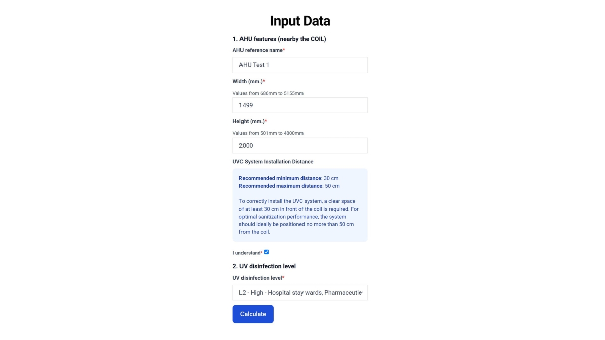
To size the UV-C system for the coil, UV-CALC HVAC COIL asks only for data the designer already has, as the input screen shows:
|
1 AHU reference name |
2 Section width, from 686 to 5155 mm |
3 Section height, from 501 to 4800 mm |
4 Installation distance: at least 30 cm of clear space in front of the coil, ideally no more than 50 cm |
5 UV disinfection level, for example L2 – High for hospital wards and pharmaceutical environments |
Click Calculate and the software returns the complete bill of materials, the microbial reduction estimate, the graphical application layout, and a PDF printout.
|
1987 year founded |
ISO 9001:2015 certified quality system |
3 locations |
CE · UL/CSA multi-standard products |
Feasibility Study and Quote
Tell us the AHU type, coil dimensions, and operating conditions, and we will work with you on sizing and the target irradiance level.
Email us at info@lightprogress.it | Contact us →
Disclaimer: This article is for general information purposes only and does not constitute regulatory or engineering advice. Results depend on installation and operating conditions.
Sources
- Building and Environment, vol. 265 (2024) 111989 — UV-C on the coils of an AHU at a Michigan medical center — DOI: 10.1016/j.buildenv.2024.111989
- Firrantello J., Bahnfleth W., Science and Technology for the Built Environment (2017), ASHRAE Research Project RP-1738 — DOI: 10.1080/23744731.2017.1402662 (Part 1) · 10.1080/23744731.2017.1383821 (Part 2)
- Luongo J.C., Brownstein J., Miller S.L., “Ultraviolet germicidal coil cleaning: Impact on heat transfer effectiveness and static pressure drop,” Building and Environment (2017) — DOI: 10.1016/j.buildenv.2016.11.022
- Menzies D. et al., “Effect of ultraviolet germicidal lights installed in office ventilation systems on workers' health and wellbeing: double-blind multiple-crossover trial,” The Lancet (2003) — DOI: 10.1016/S0140-6736(03)14897-0
- ASHRAE Handbook — HVAC Applications, chapter “Ultraviolet Air and Surface Treatment”
- ASHRAE Standard 241 — Control of Infectious Aerosols
- WELL Building Standard v2, Feature A14 “Microbe and Mold Control”
- USGBC LEED v4.1